After being promising for a long time a Plasma Globe to my child Matias (born 1988), I eventually found some "spare time" for designing one. Matias himself assembled the oscillator built around the 555 integrated circuit, while I assembled the power stage and the glass globe.
|
| |
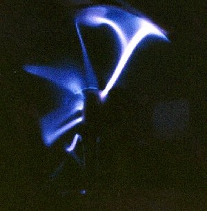
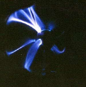
| Exposure: 800 ASA, 2.8, 1/15 | Exposure: 800 ASA, 2.8, 1/15 | |
|
| |
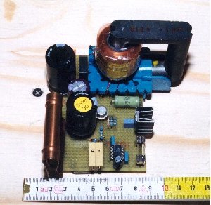
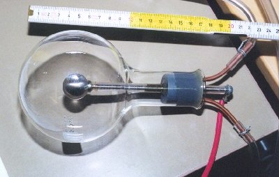
| The Plasma Globe driver: note the small copper heatsink for Q2 | The Plasma Globe: a 10 cm o.d. glass bottle |
R2 and R3 allow to change independently the 555 output low and high state duration, spanning a frequency range of about 5 to 30 kHz. The best resonance frequency for the particular TV flyback transformer I used turned out to be around 10 kHz. C3, C4, D7 and D8 make a voltage doubler feeding the transformer with about 70 VDC. D3 protects Q2 from reverse voltage.
TX1 draws from the 70 VDC power supply only 100 mA! That turns into Q2 requiring only a minimal heatsink, what is a noticeable benefit compared with the majority of plasma globe designs, typically drawing several amperes and demanding huge heatsinks. This result has been achieved by having TX1 excited at its resonance frequency, reducing current consumption at a minimum.
The globe itself consists in a chemistry glass bottle with a PVC cap. A treated rod is screwed into the cap, terminating in a stainless steel doorknob (the internal electrode). The rod is covered by some length of clear PVC tubing, to allow spark generation only from the doorknob. Two copper pipes are fitted also to the cap, one to let some gas (e.g. neon) in and the other to suck all air out with a pump. All parts are glued together with abundant epoxy.
The Plasma Globe is still waiting for a decent enclosure and a neon fill...